Receiver Control Window
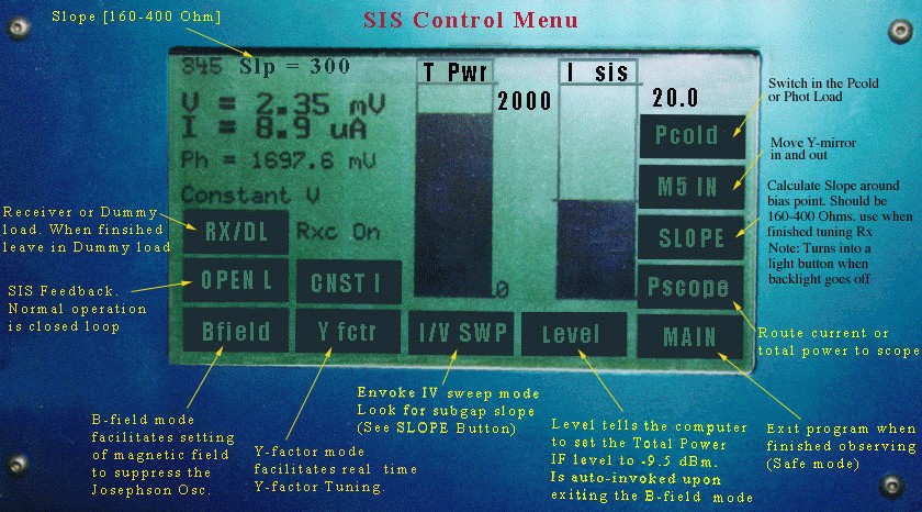
Start Tuning the Receiver by:
- Select Closed Loop (press "CLSD L"), which will default to Constant voltage as
shown on the screen above.
NOTE: Constant current is not reccomended.
- Press the RX/DL button to switch from dummy load (DL) to receiver (RX).
Switch from Receiver mode to Dummy mode when finished observing.
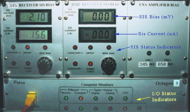
- Set the SIS bias on the manual bias box of the appropriate receiver to approx 2.0-2.3mV.
- Tune up the LO in the usual way. If you are already tuned, you should see 7-11 uA of SIS junction current
(displayed below the SIS bias voltage on the manual bias box, as well as
on the hand held display/touchscreen above). If not, follow the procedure below.
- Put some current on the junction, 10uA would be typical.
- Press the
button to apply magnetic field to the junction in order to suppress the Josephson currents.
- Press the
button to check the junction sub-gap slope.
- Press the
to have the computer set the IF output power to -9.5 dBm (+-1dB).
- Press the
button to calculate the sub-gap resistance around the SIS bias point.
This should be 160-400 Ohm.
General Tuning Princials edited from Notes by Antony Schinckel
- Tuning the 230 GHz Receiver, General Principles
- Tuning the 345 GHz Receiver, General Principles
- Tuning the 492 GHz Receiver, General Principles
- Tuning the 650 GHz Receiver, General Principles