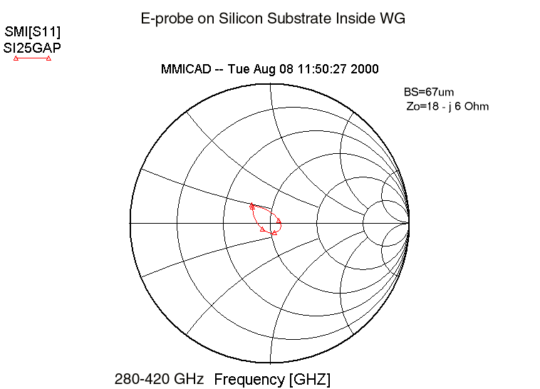
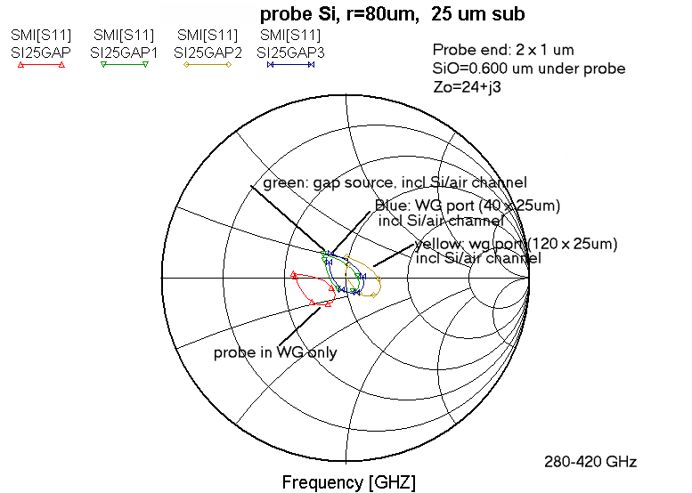
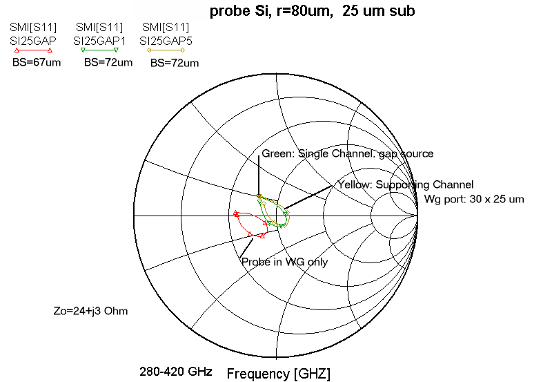
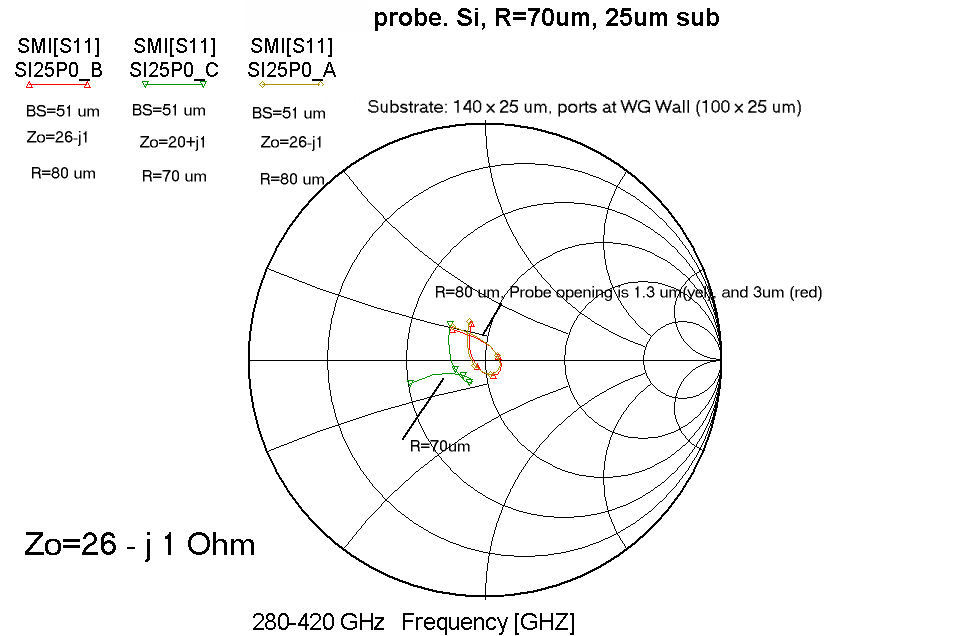
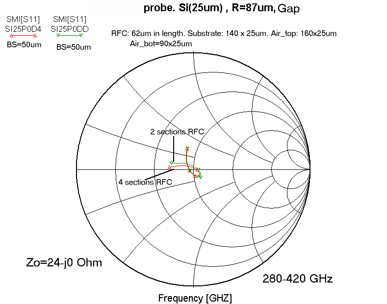
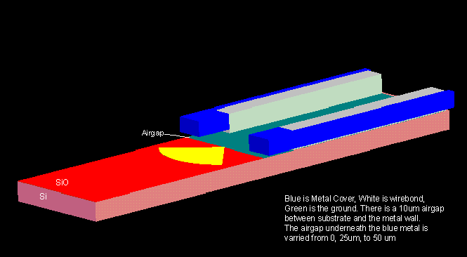
Impedance (Smith Chart) showing effect of taking probe out of the waveguide: Note also that the "gap source" simulation has no air directly above substrate, has
25 µm airgap underneath the subtrate,
and behaves very similar to the case of a very small (40 x 25 µm) waveguide port.
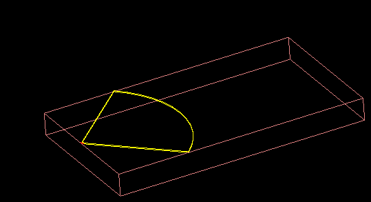
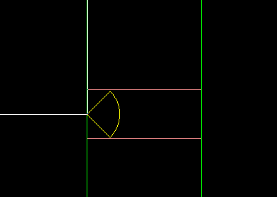
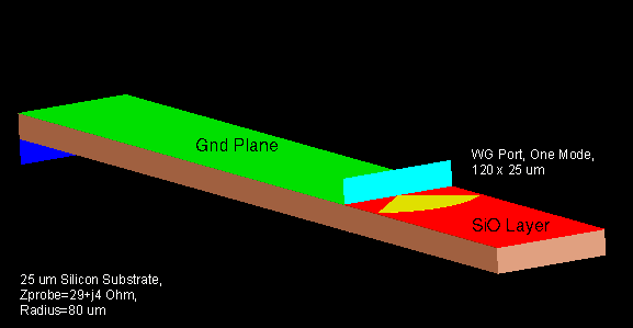
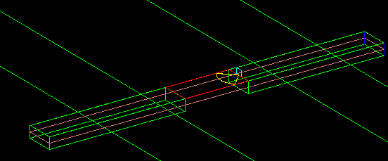
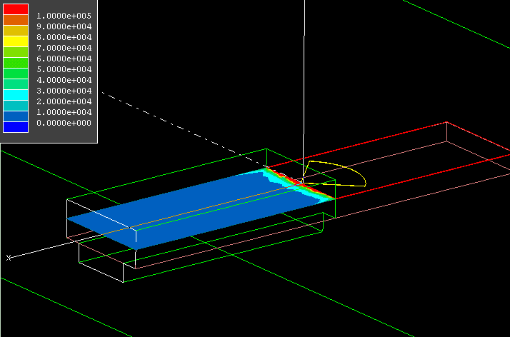
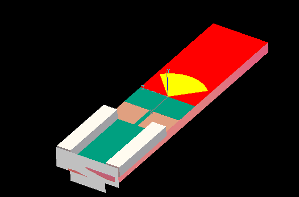
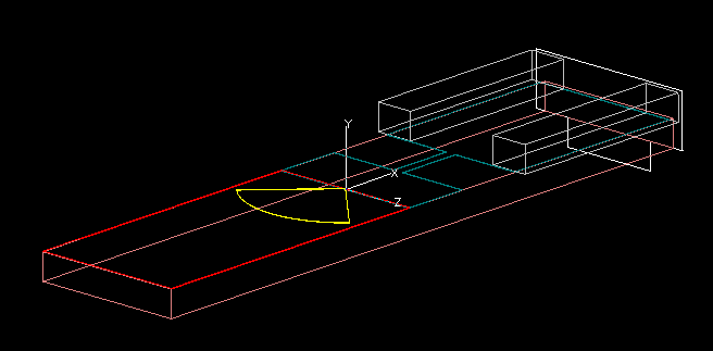
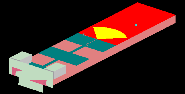
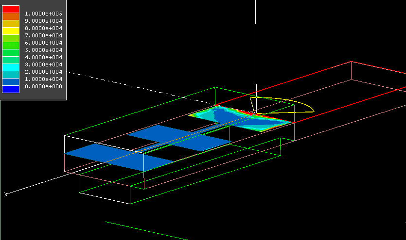
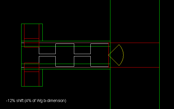
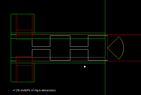
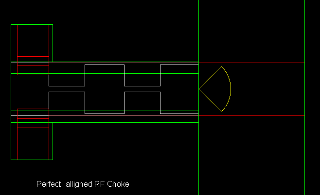
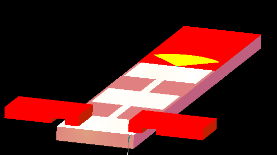
Effect of exctending substrate for structural support across the waveguide
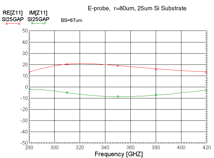
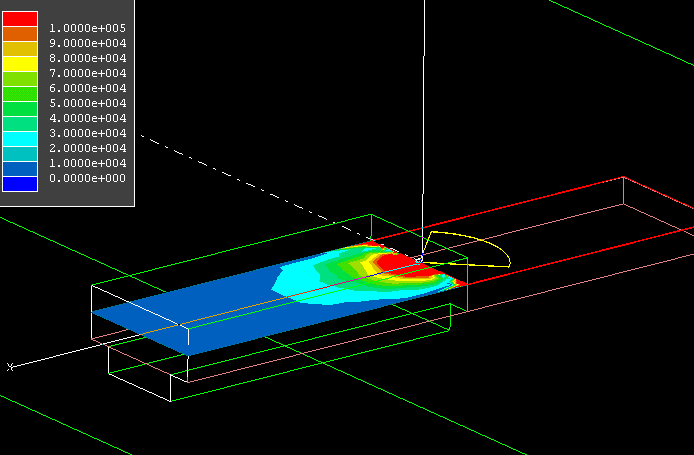
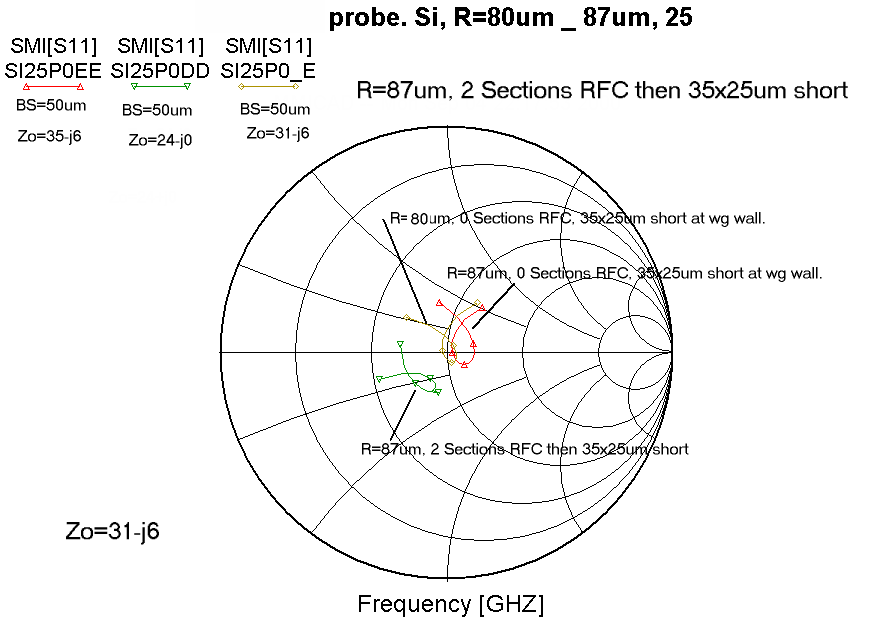
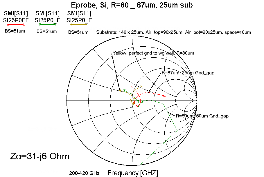
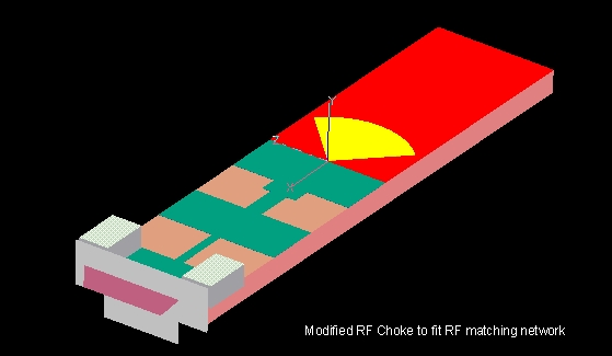
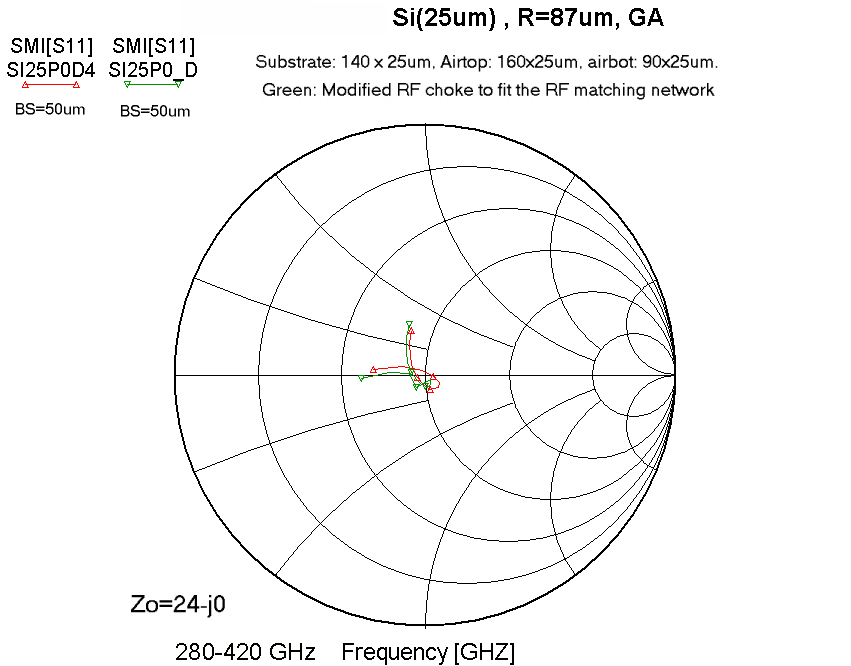
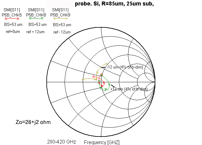
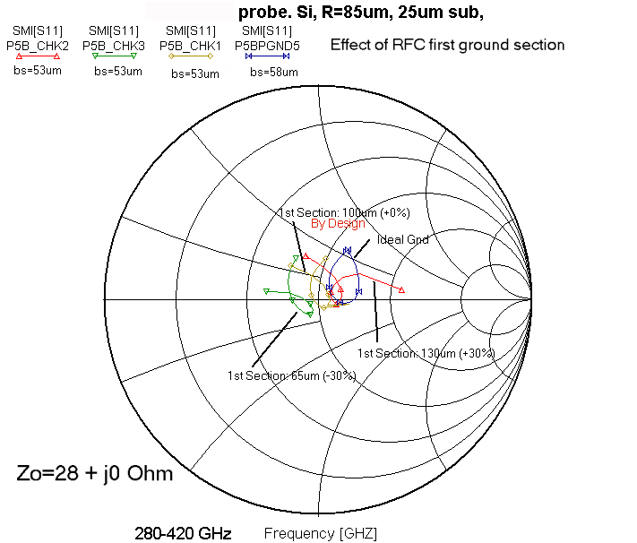
Impedance (Smith Chart) for both perfect ground and 2-Section RF Choke.Note that the significant reduction
of Probe impedance (real and imaginary) when the ground is no longer touching the waveguide wall. This effect
has been confirmed with scale model measurements. In addition, increasing the probe radius,
changes it's shape and slightly raises the impedance. It has also been observed that increasing the substrate material
changed the Probe's reactive component, and increasing the airgap at the wg Wall effects the probe's real impedance.