SHARC II Electronics
Electronics Topics:
amplifiers
battery
analog control
multiplexer
A/D (analog-to-digital)
acquisition computer and DSP
thermometry
miscellaneous notes
Amplifier Electronics
SHARC II has 12 amplifier modules,
each handling the signals from 32 bolometers. There is a 13th enclosure
which has the same shape as the amplifiers (but no multiplexer unit);
this is used for thermometry. The
thermometry unit should never be swapped with the amplifiers.
It is labeled "Thermometry" and marked with green marker to distinguish
it.
Each amplifier unit contains 8 amplifier cards, 0-1 bias cards,
and 0-2 PID/thermometry cards. The amplifier units have limited
interchangeability due to differences in the configuration of those
cards from unit to unit. At this time, amplifiers should not be
swapped without first consulting with Darren Dowell. There is at
least one spare amplifier unit in the lounge.
The amplifier attaches to the cryostat via an RFI box, so called because it has a 78-pin RFI-filtered
D connector on its output. The wiring internal to each RFI box connects
in turn to the cryostat via a circular 79-pin connector which mates with
the hermetic connector on the cryostat. An RFI box can be removed
by removing the screws holding it to the hermetic connector plate, lifting
the box gently, and reaching under to de-mate the circular connector. RFI
boxes also have limited interchangeability.
List of amplifier channels disabled on amplifier cards due to lack of response
or high noise (updated 2003 Aug. 26):
Row 1:  cols. 1, 2, 4, 32
Row 2:  col. 27
Row 3:
Row 4:  cols. 3, 4, 7, 14, 31
Row 5:  col. 1
Row 6:  col. 20
Row 7:  col. 32
Row 8:
Row 9:  col. 20
Row 10:
Row 11:
Row 12:  cols. 3, 8, 21, 24, 26
Amplifier Battery
The amplifier battery is located downstairs.
It is charged by a National Railway
Supply unit. The "charge" mode or "operate" mode can be selected
with the downstairs control panel,
or, more conveniently, the alidade control
panel.
Analog Control Electronics
The analog electronics control chassis
distributes power from the amplifier battery and routes programming signals
from the sharcii computer and user to the amplifiers. There are several
switches on the front panel that control the operation of the unit. The
switch on the bias master should be set to divide by "2N+2" for normal
operation. All of the "high/low" switches on the slave cards
should be set to "low". The "on/off" switches on odd slaves
should be set to "off"; the switches on even slaves should be set
to "on".
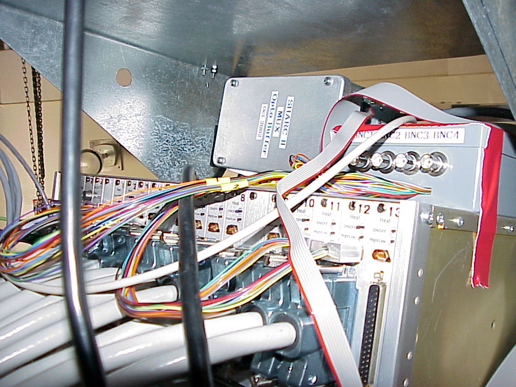
Multiplexer Electronics
The outputs of each amplifier are routed through a 2-to-1 multiplexer. The multiplexer control originates
in the analog electronics control chassis and passes through a buffer before connecting to the multiplexers in
a daisy-chain fashion. The sharcii acquisition computer is made aware
of the multiplexer state via a long cable from the second multiplexer buffer
output. The switch on the buffer box should be in the "normal" position.
A/D Electronics
The analog-to-digital converter collects
analog signals from the amplifiers/multiplexers and sends digital signals
via fiber optic cables to the sharcii computer. In unusual circumstances
(e.g., following power-up), the A/D converter malfunctions and does not
provide correct signals to the DSP. In such cases, pressing the red
reset button on the front of the A/D should return the A/D to the
proper state. After pressing the reset button, it is essential
to reset the DSP also.
The A/D power supply is downstairs and should
always be powered on at 6.0 V and -7.0 V. The typical current draw is
+2.7 A and -2.3 A.
Acquisition Computer and DSP
The sharcii computer resides in the
Lounge. From left to right, the boards in the computer are:
- Themis CPU, with Ethernet and dumb terminal connections on the
front and a serial port on the back (routed to the front panel of the computer)
- WWV/IRIG-B timing board, with BNC cable to antenna computer for
time sychronization.
- Pentek DSP board, with fiber optic cables to A/D converter
- "homemade" input port which provides multiplexer status from MUX
buffer to DSP board
- SBS I/O board, with cable from port C to analog electronics control
chassis
The IP address of sharcii is 128.171.86.12.
Thermometry Electronics
Except for JFET diodes and heaters, cryogenic thermometry and control
is routed through the special thermometry enclosure, which is labeled and
identified by green markings. We currently read only two thermometers
(detector GRT and a diode on one of two charcoal pumps in the 3He refrigerator),
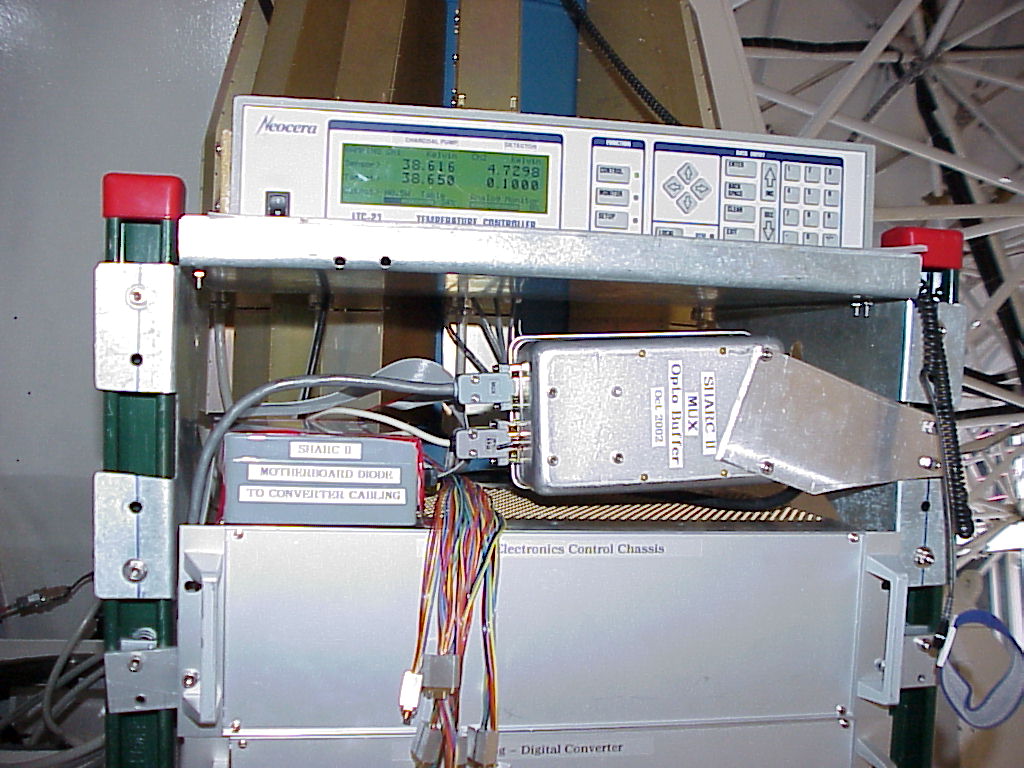
which is accomplished with the Neocera LTC-21
on the top of the rack. The Neocera also heats the charcoal pumps in
order to recycle the 3He refrigerator. Here is the
manual for the LTC-21.
A motherboard diode interface is
under test. It routes diodes located in and read in selected amplifiers
to the A/D converter.
Miscllaneous Notes
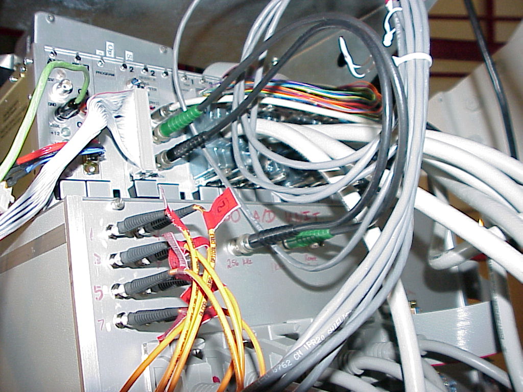
Here are some photos of the rack configuration in August 2003:
This file last updated on