Measurements of Stimulator (IR Source)
Darren Dowell -- (626)395-6675 (office), -2600 (lab), 796-8806 (FAX)
Last modified Wednesday, 11-July-2001 9:48 PDT
cdd@submm.caltech.edu
Radiation and Electrical Properties -- July 2001
Devices
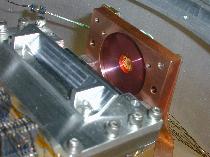
The stimulator under test was provided by M. Jhabvala (NASA-GSFC) and is of the
type used for SIRTF. We tested die 060-055.
Conclusions
When heated to 100-300 K, the stimulator produces plenty of signal in
a broad infrared band for detection by a bolometer. We observed on the order
of 1-10 pW detected by a 1 mm x 1 mm bolometer located 40 mm away. The time
constant (1/e-folding time) of the stimulator is < 1 msec and is therefore
useful for measuring bolometer radiation time constants > 1 msec.
It is unclear (untested) whether the stimulator produces enough signal in a
narrow far-IR band to be useful for detector absorptivity measurements.
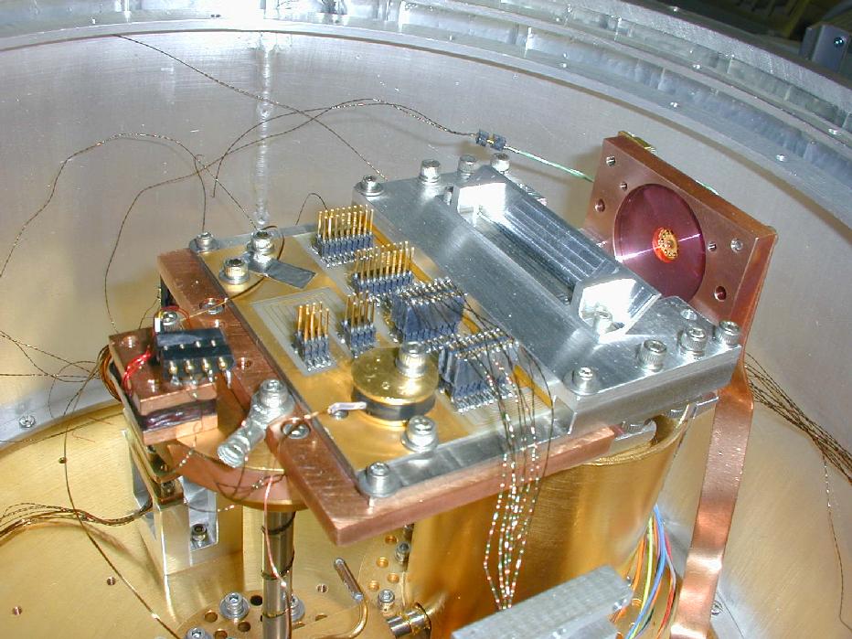
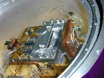
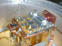
Experimental Set Up
The measurements were performed in the Barney cryostat. During the tests with
bolometers exposed to unfiltered radiation from the interior of the cryostat,
we observed a radiation leak of approx. 60 pW per detector with the stimulators
off. The radiation leak was stable over two cooldowns and did not interfere
with the stimulator measurements reported here.
The bolometer array used for the measurements was 5327 LH5, a "G0 assortment
pack" from the Spring 2000 calibration run. The array was recently coated with
a SHARC II-like bismuth absorbing film. The bolometers were approx. 40 mm
from the stimulator.
Electrical Properties
The stimulator was successfully driven with both constant current and constant
voltage excitation. The resistance of the device has a strong temperature
dependence as shown below:
Figure. Resistance of device 060-055 vs. temperature. The excitation
was 1 mV at high temperatures and 100 microV at low temperatures and was
observed to produce negligible heating in the device. The green curve shows
measurements by D. Robinson (NASA-GSFC) for a separate device. Heating by
the 10 microA current excitation is evident at low temperatures.
The resistance of the device is used to estimate the temperature under load.
The electrical time constant is measured by exciting with a constant current
and observing the settling of the voltage (or vice versa). For heating from
4 K to approx. 300 K, the electrical time constant was < 0.4 msec.
Radiation Produced
The stimulator and bolometer array were cooled down twice -- once with no
filter, and once with a silicon wafer (396 microns thick) in front of the
stimulator. Silicon should block all optical light and some bands in the
near and mid infrared.
Measurement details are available.
With an excitation of 1.4 V, which heated the device to approx. 300 K,
signals of ~18 pW and ~5 pW were observed in the unfiltered and filtered cases.
With an excitation of 0.58 V, which heated the device to approx. 80 K,
signals of ~0.42 pW and ~0.30 pW were observed in the unfiltered and filtered
cases. When the stimulator was warmer, a greater fraction of the radiation was
blocked by the silicon, indicating the expected shift in the spectrum toward
shorter wavelengths.
Radiation Time Constants
Both radiation and electrical time constants were
performed.
For the type 3A bolometers with large bias voltage, radiation time constants of
approx. 1.0 msec were observed, verifying the speed of the stimulator.
Examples of measurements:
 slow radiation time constant
 fast radiation time constant
 slow electrical time constant
 fast electrical time constant
Go to SHARC II home page...