SHARC II Installation Guide
Darren Dowell -- (626)395-6675 (office), 796-8806 (FAX)
Last modified Tuesday, 13-January-2004 19:18 PDT
cdd@submm.caltech.edu
THIS PAGE IS UNDER DEVELOPMENT
Installation Topics:
relay optics preparation
cryostat installation
electronics installation
cabling
power-up check
Relay Optics Preparation
SHARC II goes on the right port of the
relay optics. Before installing the cryostat, verify that
the right rotator is functional with the UIP "ROTATOR /RIGHT" command.
If it has not been homed since installing the relay optics, do
so, using the instructions
on the main CSO web page. Finally, set the rotator in position
for the cryostat installation: "ROTATOR /RIGHT 0".
OPTIONAL optical alignment: Using the Hertz mounting plate and the acrylic
screen, it is possible to adjust the relay optics mirrors so that
the beam from
the secondary mirror lands on the rotation axis of SHARC II. As a
first step, turn the bottom "turntable" mirror M3 full
counterclockwise.
Next, install the Hertz mounting plate (which has rectangular
standoffs)
on the rotator. The acrylic screen goes on top of that.
With
the optical path clear, and with the dome open part way, a silhouette image of the secondary mirror
should form on the screen. Adjust the rotation of M3 and tilt of
the
ellipsoidal mirror (M5) to center the silhouette in the circle on the
screen.
One should also verify that the circle is centered on the
rotation
axis by spinning the rotator. If not, reposition the screen.
In any case, the 3 relay optics mirrors feeding SHARC II should be
rigidly positioned. Some of the screws have a tendency to become
loose over time.
Cryostat Installation
The black mounting plate on the under side of SHARC II is integral to
the cryostat; the cryostat goes directly on the rotator without
any additional interface. SHARC II is normally lifted with eyebolts on the top
ring. Please run an additional strap as a safety against failure
of the eyebolts and/or top ring.
SHARC II attaches to the rotator with 8 each 1/4"-20x1" screws.
The precise alignment of the tapped holes in the black mounting
plate with
the thru holes in the rotator is a little difficult since they cannot
be
viewed easily. A solution is to thread one or two tapered
alignment
pins into the holes in the mounting plate. The alignment pins
should
be unthreaded and replaced with screws at the end of the installation.
The base of SHARC II is numbered to match the labels on the rotator.
With the rotator at 0 degrees, the helium fill tube of SHARC II
should be at the back (away from control room), and the filter wheel in
front
(toward the control room).
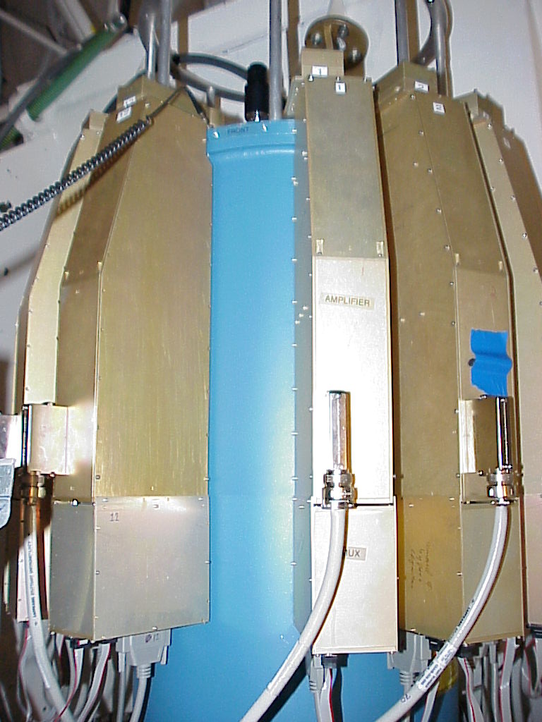
Electronics Installation
ESD GUIDELINE: Please wear ESD wrist strap to cryostat when
connecting or disconnecting RFI boxes, amplifiers, and thermometry
enclosures.
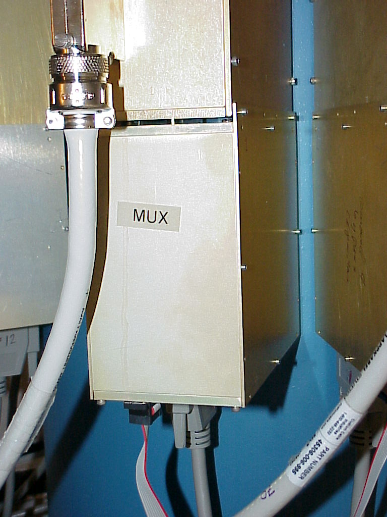
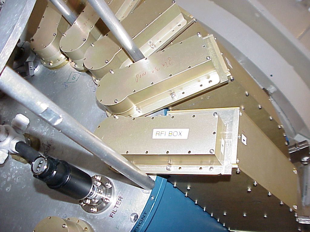
List of required components:
- 12 amplifiers (numbered 1-12),
with attached multiplexers, which get
connected
to RFI boxes 1-12
- 1 thermometry enclosure (#13; green markings), which gets
connected
to RFI box 13
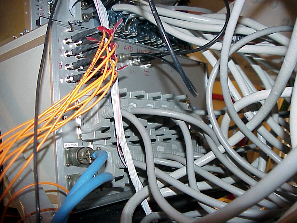
- A/D unit (12U height), on bottom
of rack
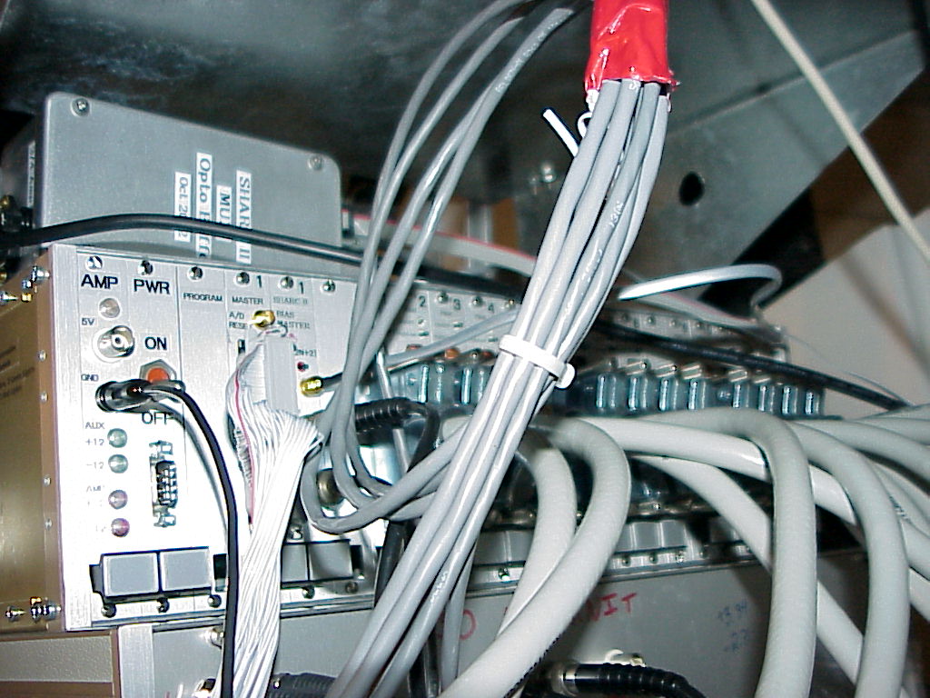
- Analog electronics control
chassis
(6U height), next up on rack
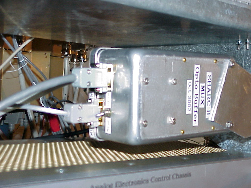
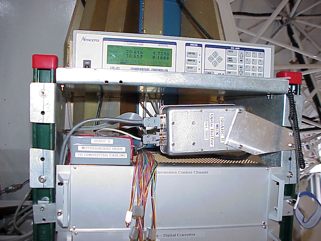
- Multiplexer buffer, between analog
electronics control chassis and shelf
- Motherboard diode to A/D
interface, next to multiplexer buffer
- Neocera temperature controller,
attached
to top shelf with electrically-isolating bracket
Cabling
ESD GUIDELINE: Please use caution to prevent electrostatic
discharge when connecting cables to SHARC II and electronics.
List of required cables:
- 12 amplifier-to-A/D cables: 37-pin D's, straight through,
molded gray, very flexible; bottom of amplifier (multiplexer) to A/D
unit;
should be arranged to accomodate full rotation of cryostat (+-90
degrees
from installation configuration)
- 12 amplifier power cables: custom light gray cables with
right angle connectors; right-angle connector on side of amplifier,
straight connector on analog electronics control chassis; should be
arranged to accomodate full rotation of cryostat
- 2 BNC cables from analog control electronics chassis to A/D unit:
one connecting 1 kHz = bias reference, other connecting 256 kHz =
demodulation reference
- AC power for multiplexer buffer
- Multiplexer buffer input signal from analog control electronics
chassis (6-pin LEMO) to multiplexer buffer (9-pin D)
- Multiplexer buffer output signal from multiplexer buffer (9-pin
D) to sharcii computer: straight through shielded circular cable
- Multiplexer signal from multiplexer buffer (9-pin D) to
multiplexer daisy-chain (9-pin D), which begins on the underside of an
amplifier (multiplexer) in the front: long (perhaps double)
ribbon cable which accomodates full rotation of cryostat
- Multiplexer signal daisy chain: 11 ribbon cables with 9-pin
D connectors which interconnect undersides of amplifiers (multiplexers)
- Programming cable: long cable from analog control
electronics unit (Centronics connector) to sharcii computer (IDC
connector, port C)
- AC power for Neocera temperature controller
- Thermometry cable: connects thermometry enclosure connector
"X" (37-pin D) to 4 connectors on back of Neocera; one dangling 15-pin
connector unused
- Neocera serial cable: connects Neocera serial port to
sharcii computer serial port; 9-pin D, straight through
- Amplifier power: connects power controller to analog
electronics control chassis; 9-pin D connector, in-line fuses
- A/D power: connects power controller to A/D unit; 2
separate cables with circular connectors, plus ground wire with banana
plug which connects to analog electronics control chassis
- 8 fiber optic cables (orange): connect A/D unit to sharcii
computer
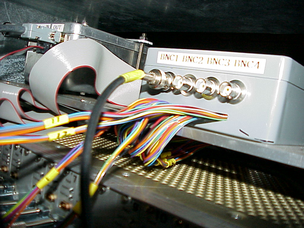
- Motherboard diode interface box to A/D unit "row 13":
37-pin D, straight through
- OPTIONAL: Motherboard diode interface box to analog
electronics control chassis: 12 each 9-pin micro-D connectors
- Motherboard diode interface box "BNC1" to chopper monitor (in sidecab): long BNC cable; should put ~900 ohm resistor
in series to dampen ringing
(ADD PHOTOS OF CABLE ROUTING LATER)
Power-Up Check
The CSO staff should ideally perform these checks instead of the
first-night astronomers:
AMPLIFIER BATTERY: It is very worthwhile to check the battery
voltages (approx. +15 V, -15 V, ground) at the SHARC
II end of the cable before plugging it in. Also, it is very
worthwhile to check that none of the conductors are shorted to the
telescope. The analog electronics has only limited protection
against problems in the
battery voltages. After these checks, the power-up sequence is the same as
performed every evening ("Powering Up the Electronics").
After the power up test, disconnect power until the instrument is
started up in the evening.
A/D POWER SUPPLY: The voltage settings are +6.0V and -7.0V, and
the currents should be in the neighborhood of +2.7A and -2.2A
when the cables are connected to the A/D unit. This power supply
stays on all the time.
NEOCERA TEMPERATURE CONTROLLER: Getting two reasonable, updating
temperatures is a necessary (but not sufficient) condition for
verifying that the 3He cycle can be carried out. The Neocera
stays on all of
the time.
Go to SHARC II home page...