Find or Make a Breakout Box
Before assembling an amplifier, first find or make a breakout box. You will need an 8 pin male connector, Hirose part number HR25-7TP-8P. I made mine with a small project box and 8 banana sockets.
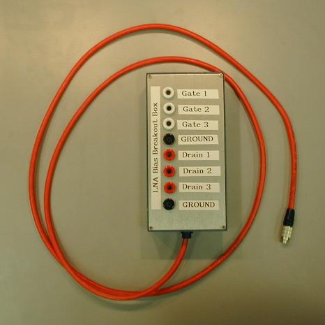
Here is the pin-out for the amplifier:
| LNA Bias Pin-Out | |
| Pin | Description |
| 1 | Gate 1 |
| 2 | Gate 2 |
| 3 | Gate 3 |
| 4 | Gate Ground |
| 5 | Drain 1 |
| 6 | Drain 2 |
| 7 | Drain 3 |
| 8 | Drain Ground |
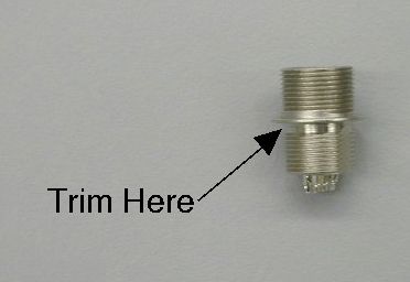
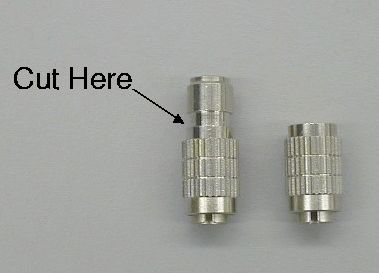
Modify the DC Bias Connectors
The female Hirose DC bias connector is only partially threaded, and therefore will not screw all the way into the block. A machinist can trim down the unthreaded area on a lathe in a couple of minutes to fix this problem. It may be noticed that the male plug is unnecessarily long. The machinist can also trim off the end on the lathe.
Install Transitions and SMA Connectors
- Visually inspect the transition circuit board, then test it on the probe station.
- Measure the channel and chip lengths. Typically, the total length will be about 0.750 inches, and the QMMIC chip length will be 0.148 inches.
- Trim the transitions to the appropriate length. Typically the input will be about 0.185 inches and the output 0.411 inches. A sharp knife works well. Inspect the transition to make sure the cut is clean and there are no short circuits.
- Test the fit.
- Using flux, tin 0.050" of the microstrip ends of the transitions.
- Tin the pins on the SMA connectors.
- Epoxy the transitions into the groove on the microwave side of the amplifier housing. Be careful to use enough epoxy to make good contact for the ground plane, but not so much that it flows into the area where the QMMIC will go shorts out the center conductor of the transition. Make sure that the transition circuits are centered so that the SMA pin will line up perfectly with the microstrip. Cure the epoxy on a hot plate or in an oven.
- Install the SMA connectors with 2-56 socket-cap screws. Put flux on the tinned areas, and touch them with a hot soldering iron to make a good electrical connection. Inspect, and test for a good connection. Make sure there are no shorts.
- Thoroughly clean out the microwave side of the housing with acetone and distilled water. Make sure there is no flux or other substance that could degrade the quality of wire bonds, etc.
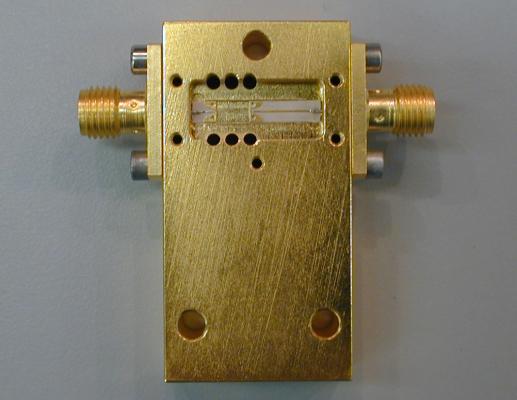
Install DC Bias Feed-Thrus
- Place the housing with the DC cavity facing up. Using a sharp needle, carefully paint the top surfaces of the two shallow depressions with silver epoxy.
- Use the needle to paint a ribbon of epoxy around the outer conductor of a feed-thru. Insert the feedthru into a hole, and use the needle to spread epoxy over the top face of the outer conductor. Continue with the other 5 feed-thrus.
- Visually inspect the feed-thrus from both cavities to check for shorts. Make sure all the pins are aligned vertically, otherwise the circuit board may not fit over the pins.
- Cure epoxy, preferably no hotter than 100° C.
- Check each pin with an Ohm meter to make sure it is not short-circuited to ground.
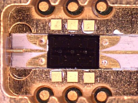
Install 100 pF Capacitors
-
Using a sharp needle, place a small dot of silver epoxy where a
capacitor will go, according to the picture, below. Place a
capacitor on the epoxy drop, being careful that the capacitor is flat
and level. Inspect capacitor edges for short circuits. Repeat
with the other 5 capacitors.
WARNING: Don't use too much epoxy, or you will short out the capacitors. - Cure epoxy, preferably no hotter than 100° C.
- Use an Ohm meter to make sure that no capacitors are not shorted out.
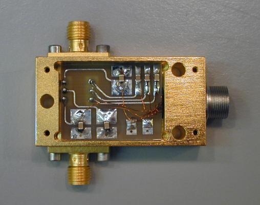
Install DC Bias Circuit and Connector
- Make sure the DC circuit board fits in the cavity over the 6 bias pins.
- Remove the board from the cavity, and solder the diodes and capacitors onto the board.
- Clean the board.
- Mount the board into the cavity using silver epoxy or low-temperature solder.
- Solder the six bias pins to the circuit board.
- Cut 8 pieces of 0.005" wire about 2" long. Strip both ends. Tin one end, then trim the tinned part to slightly longer than the solder cups on the Hirose receptacle are deep.
- Tin the Hirose connector (if it isn't already) and solder on the 8 wires. Inspect the solder job, tug on the wires, and test for continuity or shorts. Clean the plug.
- Screw the plug into the amplifier block.
- Use the break-out box to figure out what each wire is. Trim the wires, strip the ends, tin them, and solder them to the circuit board.
- Clean any flux out of the cavity.
- Turn the amplifier housing over, and use the break-out box to test that the signal is getting to the pins in the microwave cavity. Test for shorts, etc.
Install QMMIC Chip
-
Make sure the chip fits in the cavity between the transition
circuits.
WARNING: Make sure your tweezers are clean and not bent before handling the chip. -
Glue the chip into the slot using some kind of glue that will
survive thermal cycling yet still allow the chip to be removed
later.
WARNING: Practice gluing dead chips before attempting to glue a good device.
WARNING: Be extremely careful not to use too much glue, or to get glue on the top of the chip or any other circuit areas! -
Wire-bond the chip. Start by going from the posts to the 100 pF
capacitors. Then do the chip.
WARNING: Don't use too much heat when wire-bonding the chip. It could melt solder or damage the DC bias connector. I had problems using 150° C. 100° is probably safe.